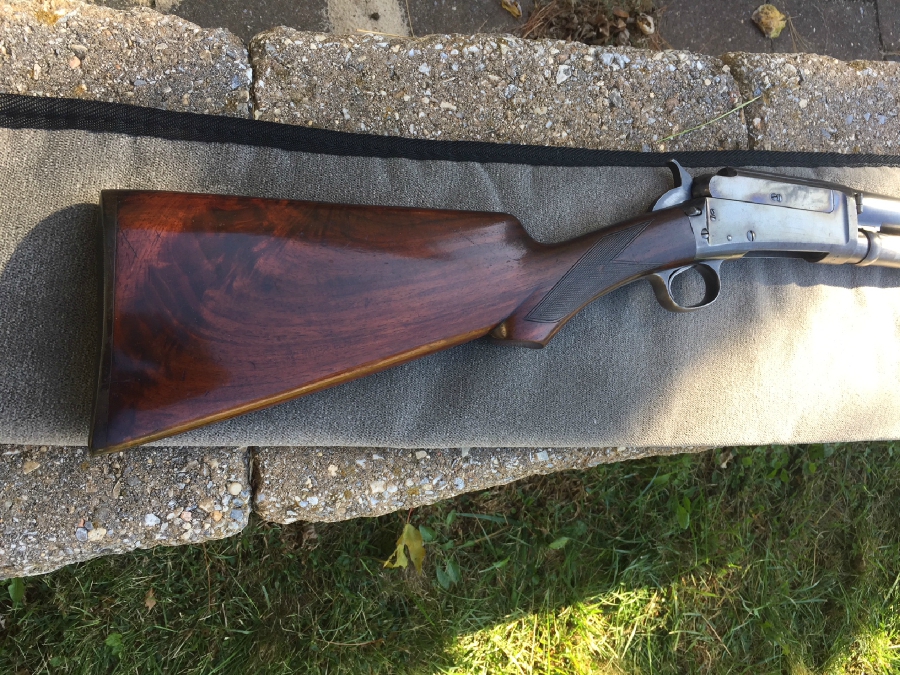
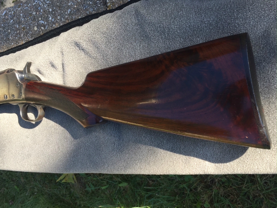
Nice wood on this scattergun!
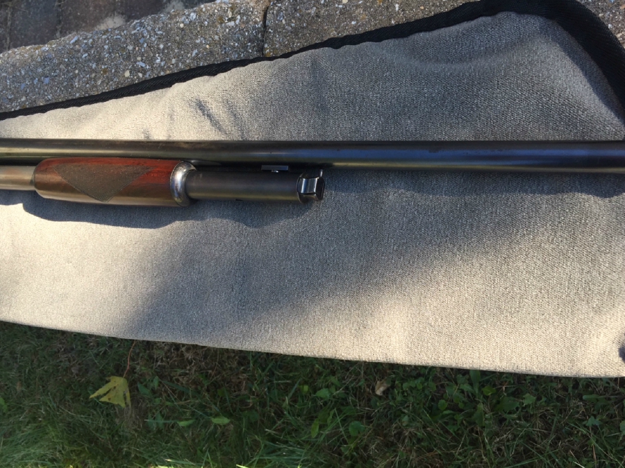
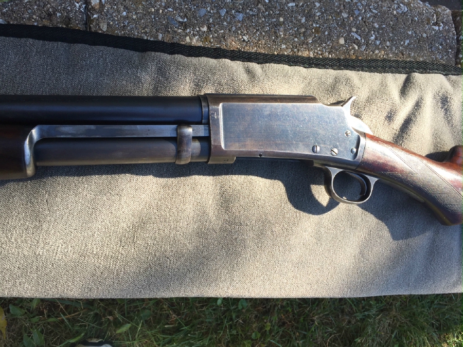


The take down model
.jpg_thumbnail0.jpg)
Marlin Hammer Pump Shotgun Disassembly in Pictures
I thought I’d write up a few of these that aren’t in the disassembly manuals as they come along.
The gun depicted here is a Model 30G in 20 gauge I restored for use by a grandchild. Sold under a hardware store label of National Firearms Company circa 1915, it has the new model recoil safety lock and pinch-block takedown, but retains the simpler wood and forearm styles of the older Models 16 and 1898. The basic mechanism however, is sufficiently close to other Marlin Hammer Pumps that this can serve as a general guide for disassembly of Models 1898, 16, 17, 19, 21, 24, 26, 42 and 49.
Avoid ordering parts unless you are sure you need them, as old guns can be so jammed with century-old oil turned to hard varnish and mixed with concreted powder residue and fragments of paper shell crimps that a detailed cleaning may be all the gun requires. They all benefit from a thorough soaking in Kroil or other thin penetrating fluid to free up frozen screws and pins. Just try to keep the oil out of the inletting.

Insure the gun is unloaded and the bore is clear. Remove the stock bolt and carefully pull off the buttstock. If you don’t take down the gun first you’ll have better control to gently strike the comb and pistol grip of a reluctant stock alternately with the heel of your hand to prevent the racking that can spit the edges of the inletting. Plus leaving the forearm slide mounted until it’s time to remove the bolt will aid the safety and function checks you’ll perform during disassembly.

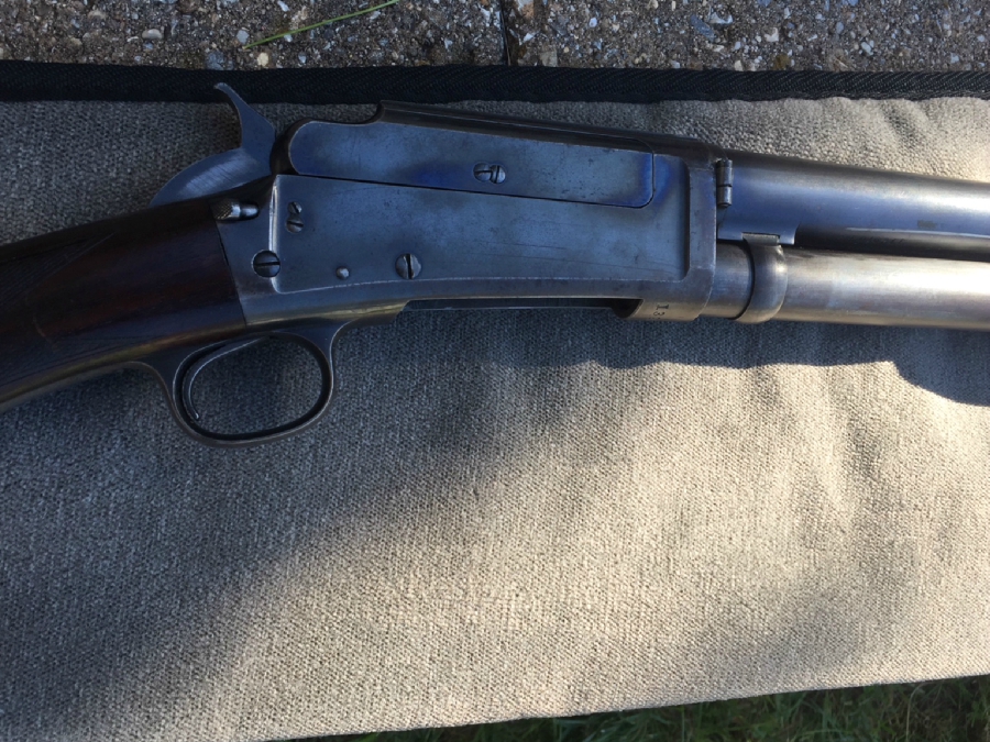
My fingers are pointing to the trigger guard screw on the left and the recoil safety lock screw on the right. Loosen the recoil lock screw but don’t remove it yet.

Remove the tension on the hammer. Loosen its mounting screw slightly, compress the hammer spring using your fingers and pull it aside from the roller block on the bottom of the hammer. Then remove the hammer screw and pull the screw from the frame, leaving the hammer loosely in place for now.

Remove both trigger guard screws, pull the trigger guard assembly from the bottom of the frame, reinstall the screws in the trigger guard and the stock bolt screw to keep track of them and set it aside. Pull the loose hammer out the bottom of the frame, remount its screw correctly oriented in its mating hole to keep track of it, and also set it aside.

Note the relationships between the carrier on the left, the recoil lock in the center, the locking bolt atop them, and the safety sear (photo below) still mounted in the frame on the right. Pulling the knurled surface of the recoil lock arm to the rear unlocks the locking bolt above it. Then gently racking the slide arm rearward clicks the bolt out of battery, and moves the carrier downward to pick up the next shell until the carrier arm strikes the shaft of the recoil lock screw. This serves as the rearward bolt stop, which is useful to understand in diagnosing any later problems.

Remount the hammer without the trigger guard and observe the interface between the safety sear and hammer. The hammer has three notches….the upper notch is engaged by the safety sear until the bolt moves forward and locks into battery, whereby a cam slot milled into the bottom of the bolt engages the cam on the top of the spring-loaded safety sear, disengaging it and allowing the hammer to engage the trigger/sear with the full and half cock notches on the lower end of the hammer.

The safety sear can be removed now. It has an integral leaf spring beneath it and pressure should be applied on it with a finger to loosen and pull its screw.

The recoil lock is spring loaded by a plunger that interfaces with the trigger guard frame, and a separate spring-loaded cam on its upper, inside surface that interfaces with a cam slot milled into the carrier.

It functions as an inertia block and must be free to pivot on its shaft. As the gun is fired the frame recoils and the block tips forward, unlocking the locking arm hook from its mating cutout on the bolt, freeing the bolt to be clicked out of battery and racked to the rear using the slide handle. If the shell hangs fire (which is rare today but was common a century ago), the inertia block doesn’t move and the hook prevents the bolt from being racked out of battery without the shooter (hopefully) pausing to think about what happened and wait the required 30 seconds before manually depressing the knurled surface of the locking arm to cycle the action.

Note the hook faces rearward, and the block, cam and carrier/frame mating surfaces are polished for easy movement. The plunger and cam have coil springs and are mounted using pins that facilitate removal for spring replacement and cleaning. When remounting, avoid over tightening the screw.

At the center inside surface of the carrier arm you can see the cutout for the recoil lock’s upper cam. The carrier is removed by dismounting its screw, lifting the arm and pulling it rearward to disengage its positioning slot from the round stud it mates with on the inside link of the locking bolt. Also note if you cycle the bolt rearward, there is no longer a bolt stop mounted and the carrier mating stud will disengage from the track at the rear of the carrier, yet the carrier will appear normal. Try this a few times to see the relationships, as this can cause problems during reassembly.

Now is time to take down the gun. Grab and squeeze the pinch block and pull the magazine tube forward until the left-side detent pin projects outward to hold it in place. Insure the bolt is in battery and pull the slide arm forward and out, disengaging it from the locking bolt link and out of the receiver. Note that the tube’s mounting screw and its corresponding bug (locking) screw are now exposed for further disassembly….the bug screw is removed first and can be accessed by grasping the pinch block and sliding the tube forward slightly. The tube should look like the top photo below.


Loosen the adjusting collar by backing out its screw and if tight, tapping it with a brass hammer. The collar and barrel threads are left-handed, so turn them to the right to loosen and remove the barrel assembly.

Remove the bolt by clicking it out of battery, pulling it all the way to the rear, and rotating the bolt’s tail to the right laterally and clockwise out of the bolt opening. The gun’s locking lug is the rear face of the frame at the bolt opening. If it or its mating surface at the rear of the locking bolt appear to be dinged up or worn, take the gun to a qualified smith and have the headspace checked before test firing. Here I’ve left the safety sear in so you can see the cam that interfaces with a corresponding shaped slot on the bottom of the locking bolt. The vertical slot next to it is the cutout for the carrier arm. Beneath the tip of the pointer is a stopped slot that can make removing and installing the bolt assembly difficult. On the outside of the locking bolt link there is a corresponding stud (photo below) that must be both in the correct position and rotated into that slot for the bolt to fit its track without jamming.

The bolt assembly as it appears when locked into battery and ready to fire. The locking lug on the frame mates with the entire rear end of the locking bolt as depicted by the pointer. Also note the cutout on the rear of the locking bolt for the recoil safety hook, and the rectangular stud (mentioned in the above paragraph) milled as part of the bolt link above the slide-arm mortise. The stud is there to insure the bolt cannot move in and out of battery except where the frame has a cutout that permits the stud to change its angle. In battery is the only position where the firing pin should project beyond the bolt face, otherwise the pin is broken. Check that. Also note the shape of the slide arm mortise that forms the major part of the bolt link, and how it interfaces with its corresponding round stud milled into the end of the slide arm.

The bolt as it appears when out of battery. Note the rectangular stud on the link is now parallel to the corresponding slot in the frame….the bolt must be out of battery to mount and dismount from the frame. In this position the firing pin should be blocked from projecting beyond the bolt face. Check that, too. Before further disassembly, click the locking bolt in and out of battery a few times to note how its spring-loaded catch functions.

Disassemble the bolt by removing the smaller bug screw and screw-slotted pin on the right side, separating the locking and the breech bolt sections. Note how the one-piece firing pin is oriented in the breech bolt, and that the locking bolt and link is a one-piece forging.

The firing pin is removed by driving out its mounting pin at the rear of the breech bolt. Once removed, note the mating slot for that pin to facilitate reassembly.

Note the two extractor mounting pins in the breech bolt. The right-hand pin also simultaneously captures the locking bolt catch and its coil spring in a corresponding slot in the catch housing.

The safest method to disassemble the extractors for cleaning is to place the breech bolt in a drill press vise or C-clamp to prevent losing parts by sudden release of spring tension. The bolt in the photo is from a Model 31, but the same relationships apply.

The same Model 31 bolt with the extractors removed and their corresponding mortises cleaned. I don’t recommend omitting this task, as mortises that appear clean enough from the outside are often full of crud and even bits of paper shell crimp, and dirty extractors that apply unequal pressure to the sides of the rim either on the forward or rearward stroke can cause a number of malfunctions not otherwise explained.

The ejector is removed by simply lifting it out of its corresponding mortise in the frame. Note it has an integral leaf spring on the back and is captured in place only by the breech bolt riding correctly in its frame slots. It can be a serious source of jamming if the spring is broken or the bolt is forced into place out of track. Some Marlin models have a screw that holds the rear of the ejector in place. This is the most vulnerable spring in the gun, because raindrops entering an open bolt easily seep into the mortise and rust the spring, eventually causing it to break. Broken or partially broken ejector springs can appear to function normally yet can be the source of a number of unexplained problems, so like the extractors, don’t fail to remove, clean and check it thoroughly. Numrich carries new-made replacements, but are oversize and require fitting.

The cartridge stops also have leaf springs integral to their rear surfaces, and also require removal to clean beneath them. Removal is via a fine, top-threaded screw with a shaft on its lower end that fits into a hole on the opposite side of the cartridge stop mortise in the frame. The screw is fragile and disassembly requires a jeweler’s screwdriver. Scrape any crud out from the top of the screwhead and clean the slot using a sharp ice pick before soaking for several days in Kroil or other thin penetrating fluid before attempting to dismantle.

Study the relationships between the stops to prevent confusion upon reassembly. Some Marlin models have a one-piece stop, this model has a two-piece stop.

Final disassembly of the trigger guard assembly for cleaning is straightforward. The trigger-sear spring is held by a screw accessed after removing the hammer spring, the gun’s sear is the tip of the trigger, and the trigger is held in place by a pin through the frame.

Final disassembly of the barrel assembly is also straightforward, here showing the relationship of the pinch block parts, with the magazine tube spring and follower still in the tube.

The forearm must be removed to dismount the forend slide from the magazine tube. This model has three mounting screws in escutcheons held in place by bug screws, later models have a full-length steel tube and the wood captured by a forend cap nut with fine, right-hand threading. A padded set of large pliers is often required to remove these cap nuts, sometimes without success. Be prepared to clean and even refinish around them rather than break the fragile forearms, which are difficult to find or turn replacements on the lathe. If your forearm wood is missing or hopeless, Wenig may have one in their CNC stock-milling software and may be able to make one for you. Model 12/97 replacement forearms are common, can be had in the 30-dollar range and may be an option, although the tube diameters are slightly different between Winchester and Marlin.

The last step is optional, which is to drive off the dovetailed magazine band from right to left using a brass punch in order to facilitate cleaning around it.
Reassembly Reminders:
The bolt is reinserted out of battery, but must be pressed all the way forward and clicked into battery for the remainder of the reassembly.
The bolt is reinserted link first from the right side of the frame with the rear of the bolt held outboard so the rectangular stud on the link can be moved forward sufficiently to engage its stopped slot in the frame. At the same time, press the ejector into its mortise in the frame and hold it place with your finger to insure it remains in its correct position.
When the pump arm pulls the bolt forward, it should automatically click the bolt into battery.
Reinstall the secondary sear after the bolt, but before the bolt is clicked into battery.
Click the bolt into battery by pushing on the front of the locking bolt link before installing the carrier. Install the carrier by engaging the front of the carrier slot into the round stud on the inside link of the locking bolt and sliding the carrier forward until its screw hole aligns with the frame.
When installing the recoil lock, don’t tighten the screw until the trigger guard is reinstalled and then tighten it only lightly.
The Model 1898 Marlin enjoyed a poor reputation because supposedly an overloaded shell fired in the original design allowed the bolt to exit the rear of the receiver, striking the shooter. I don’t know about the original design, but to accomplish that with this gun, it would have to (1) fire out of battery and the (2) forged carrier arm, the (3) recoil lock screw shaft, and the (4) forged locking bolt link would all have to break…a practical impossibility. While the steel in these is softer than in modern-made guns and the barrels are thinner and lighter, if in good condition, properly maintained, and checked by a qualified gunsmith beforehand, I don’t hesitate to use them with a light diet of low-pressure loadings and lead (never steel) shot. They are certainly as safe as the fabled Model 12’s and Model 97’s of similar vintage few have second thoughts about shooting. Guns of any make I would hesitate shooting without further evaluation include those with dinged or worn locking lugs, badly pitted bores, short chambers, badly dented or bulged barrels, twist or Damascus barrels and those made before 1900 and proofed only for black powder.
Last is a reminder that these old pump guns are all “slam-fire” guns that lack the trigger disconnects present on modern guns. Hold the trigger back and the gun fires immediately as the bolt goes into battery. This makes them faster to shoot, but entirely unforgiving about lack of trigger discipline. Insure you and your students keep fingers out of trigger guards until ready to shoot. While the older Marlin hammerless pumps have their safety catches inside the trigger guard and are often called ”slam-fire guns with suicide safeties”, remember that because they cycle straight to the full-cock notch, all the hammer guns are “slam-fire guns with no safeties”.
Additional References: http://marauder.homestead.com/files/Marlin98s.htm
The gun depicted here is a Model 30G in 20 gauge I restored for use by a grandchild. Sold under a hardware store label of National Firearms Company circa 1915, it has the new model recoil safety lock and pinch-block takedown, but retains the simpler wood and forearm styles of the older Models 16 and 1898. The basic mechanism however, is sufficiently close to other Marlin Hammer Pumps that this can serve as a general guide for disassembly of Models 1898, 16, 17, 19, 21, 24, 26, 42 and 49.
Avoid ordering parts unless you are sure you need them, as old guns can be so jammed with century-old oil turned to hard varnish and mixed with concreted powder residue and fragments of paper shell crimps that a detailed cleaning may be all the gun requires. They all benefit from a thorough soaking in Kroil or other thin penetrating fluid to free up frozen screws and pins. Just try to keep the oil out of the inletting.
Insure the gun is unloaded and the bore is clear. Remove the stock bolt and carefully pull off the buttstock. If you don’t take down the gun first you’ll have better control to gently strike the comb and pistol grip of a reluctant stock alternately with the heel of your hand to prevent the racking that can spit the edges of the inletting. Plus leaving the forearm slide mounted until it’s time to remove the bolt will aid the safety and function checks you’ll perform during disassembly.
My fingers are pointing to the trigger guard screw on the left and the recoil safety lock screw on the right. Loosen the recoil lock screw but don’t remove it yet.
Remove the tension on the hammer. Loosen its mounting screw slightly, compress the hammer spring using your fingers and pull it aside from the roller block on the bottom of the hammer. Then remove the hammer screw and pull the screw from the frame, leaving the hammer loosely in place for now.
Remove both trigger guard screws, pull the trigger guard assembly from the bottom of the frame, reinstall the screws in the trigger guard and the stock bolt screw to keep track of them and set it aside. Pull the loose hammer out the bottom of the frame, remount its screw correctly oriented in its mating hole to keep track of it, and also set it aside.
Note the relationships between the carrier on the left, the recoil lock in the center, the locking bolt atop them, and the safety sear (photo below) still mounted in the frame on the right. Pulling the knurled surface of the recoil lock arm to the rear unlocks the locking bolt above it. Then gently racking the slide arm rearward clicks the bolt out of battery, and moves the carrier downward to pick up the next shell until the carrier arm strikes the shaft of the recoil lock screw. This serves as the rearward bolt stop, which is useful to understand in diagnosing any later problems.
Remount the hammer without the trigger guard and observe the interface between the safety sear and hammer. The hammer has three notches….the upper notch is engaged by the safety sear until the bolt moves forward and locks into battery, whereby a cam slot milled into the bottom of the bolt engages the cam on the top of the spring-loaded safety sear, disengaging it and allowing the hammer to engage the trigger/sear with the full and half cock notches on the lower end of the hammer.
The safety sear can be removed now. It has an integral leaf spring beneath it and pressure should be applied on it with a finger to loosen and pull its screw.
The recoil lock is spring loaded by a plunger that interfaces with the trigger guard frame, and a separate spring-loaded cam on its upper, inside surface that interfaces with a cam slot milled into the carrier.
It functions as an inertia block and must be free to pivot on its shaft. As the gun is fired the frame recoils and the block tips forward, unlocking the locking arm hook from its mating cutout on the bolt, freeing the bolt to be clicked out of battery and racked to the rear using the slide handle. If the shell hangs fire (which is rare today but was common a century ago), the inertia block doesn’t move and the hook prevents the bolt from being racked out of battery without the shooter (hopefully) pausing to think about what happened and wait the required 30 seconds before manually depressing the knurled surface of the locking arm to cycle the action.
Note the hook faces rearward, and the block, cam and carrier/frame mating surfaces are polished for easy movement. The plunger and cam have coil springs and are mounted using pins that facilitate removal for spring replacement and cleaning. When remounting, avoid over tightening the screw.
At the center inside surface of the carrier arm you can see the cutout for the recoil lock’s upper cam. The carrier is removed by dismounting its screw, lifting the arm and pulling it rearward to disengage its positioning slot from the round stud it mates with on the inside link of the locking bolt. Also note if you cycle the bolt rearward, there is no longer a bolt stop mounted and the carrier mating stud will disengage from the track at the rear of the carrier, yet the carrier will appear normal. Try this a few times to see the relationships, as this can cause problems during reassembly.
Now is time to take down the gun. Grab and squeeze the pinch block and pull the magazine tube forward until the left-side detent pin projects outward to hold it in place. Insure the bolt is in battery and pull the slide arm forward and out, disengaging it from the locking bolt link and out of the receiver. Note that the tube’s mounting screw and its corresponding bug (locking) screw are now exposed for further disassembly….the bug screw is removed first and can be accessed by grasping the pinch block and sliding the tube forward slightly. The tube should look like the top photo below.
Loosen the adjusting collar by backing out its screw and if tight, tapping it with a brass hammer. The collar and barrel threads are left-handed, so turn them to the right to loosen and remove the barrel assembly.
Remove the bolt by clicking it out of battery, pulling it all the way to the rear, and rotating the bolt’s tail to the right laterally and clockwise out of the bolt opening. The gun’s locking lug is the rear face of the frame at the bolt opening. If it or its mating surface at the rear of the locking bolt appear to be dinged up or worn, take the gun to a qualified smith and have the headspace checked before test firing. Here I’ve left the safety sear in so you can see the cam that interfaces with a corresponding shaped slot on the bottom of the locking bolt. The vertical slot next to it is the cutout for the carrier arm. Beneath the tip of the pointer is a stopped slot that can make removing and installing the bolt assembly difficult. On the outside of the locking bolt link there is a corresponding stud (photo below) that must be both in the correct position and rotated into that slot for the bolt to fit its track without jamming.
The bolt assembly as it appears when locked into battery and ready to fire. The locking lug on the frame mates with the entire rear end of the locking bolt as depicted by the pointer. Also note the cutout on the rear of the locking bolt for the recoil safety hook, and the rectangular stud (mentioned in the above paragraph) milled as part of the bolt link above the slide-arm mortise. The stud is there to insure the bolt cannot move in and out of battery except where the frame has a cutout that permits the stud to change its angle. In battery is the only position where the firing pin should project beyond the bolt face, otherwise the pin is broken. Check that. Also note the shape of the slide arm mortise that forms the major part of the bolt link, and how it interfaces with its corresponding round stud milled into the end of the slide arm.
The bolt as it appears when out of battery. Note the rectangular stud on the link is now parallel to the corresponding slot in the frame….the bolt must be out of battery to mount and dismount from the frame. In this position the firing pin should be blocked from projecting beyond the bolt face. Check that, too. Before further disassembly, click the locking bolt in and out of battery a few times to note how its spring-loaded catch functions.
Disassemble the bolt by removing the smaller bug screw and screw-slotted pin on the right side, separating the locking and the breech bolt sections. Note how the one-piece firing pin is oriented in the breech bolt, and that the locking bolt and link is a one-piece forging.
The firing pin is removed by driving out its mounting pin at the rear of the breech bolt. Once removed, note the mating slot for that pin to facilitate reassembly.
Note the two extractor mounting pins in the breech bolt. The right-hand pin also simultaneously captures the locking bolt catch and its coil spring in a corresponding slot in the catch housing.
The safest method to disassemble the extractors for cleaning is to place the breech bolt in a drill press vise or C-clamp to prevent losing parts by sudden release of spring tension. The bolt in the photo is from a Model 31, but the same relationships apply.
The same Model 31 bolt with the extractors removed and their corresponding mortises cleaned. I don’t recommend omitting this task, as mortises that appear clean enough from the outside are often full of crud and even bits of paper shell crimp, and dirty extractors that apply unequal pressure to the sides of the rim either on the forward or rearward stroke can cause a number of malfunctions not otherwise explained.
The ejector is removed by simply lifting it out of its corresponding mortise in the frame. Note it has an integral leaf spring on the back and is captured in place only by the breech bolt riding correctly in its frame slots. It can be a serious source of jamming if the spring is broken or the bolt is forced into place out of track. Some Marlin models have a screw that holds the rear of the ejector in place. This is the most vulnerable spring in the gun, because raindrops entering an open bolt easily seep into the mortise and rust the spring, eventually causing it to break. Broken or partially broken ejector springs can appear to function normally yet can be the source of a number of unexplained problems, so like the extractors, don’t fail to remove, clean and check it thoroughly. Numrich carries new-made replacements, but are oversize and require fitting.
The cartridge stops also have leaf springs integral to their rear surfaces, and also require removal to clean beneath them. Removal is via a fine, top-threaded screw with a shaft on its lower end that fits into a hole on the opposite side of the cartridge stop mortise in the frame. The screw is fragile and disassembly requires a jeweler’s screwdriver. Scrape any crud out from the top of the screwhead and clean the slot using a sharp ice pick before soaking for several days in Kroil or other thin penetrating fluid before attempting to dismantle.
Study the relationships between the stops to prevent confusion upon reassembly. Some Marlin models have a one-piece stop, this model has a two-piece stop.
Final disassembly of the trigger guard assembly for cleaning is straightforward. The trigger-sear spring is held by a screw accessed after removing the hammer spring, the gun’s sear is the tip of the trigger, and the trigger is held in place by a pin through the frame.
Final disassembly of the barrel assembly is also straightforward, here showing the relationship of the pinch block parts, with the magazine tube spring and follower still in the tube.
The forearm must be removed to dismount the forend slide from the magazine tube. This model has three mounting screws in escutcheons held in place by bug screws, later models have a full-length steel tube and the wood captured by a forend cap nut with fine, right-hand threading. A padded set of large pliers is often required to remove these cap nuts, sometimes without success. Be prepared to clean and even refinish around them rather than break the fragile forearms, which are difficult to find or turn replacements on the lathe. If your forearm wood is missing or hopeless, Wenig may have one in their CNC stock-milling software and may be able to make one for you. Model 12/97 replacement forearms are common, can be had in the 30-dollar range and may be an option, although the tube diameters are slightly different between Winchester and Marlin.
The last step is optional, which is to drive off the dovetailed magazine band from right to left using a brass punch in order to facilitate cleaning around it.
Reassembly Reminders:
The bolt is reinserted out of battery, but must be pressed all the way forward and clicked into battery for the remainder of the reassembly.
The bolt is reinserted link first from the right side of the frame with the rear of the bolt held outboard so the rectangular stud on the link can be moved forward sufficiently to engage its stopped slot in the frame. At the same time, press the ejector into its mortise in the frame and hold it place with your finger to insure it remains in its correct position.
When the pump arm pulls the bolt forward, it should automatically click the bolt into battery.
Reinstall the secondary sear after the bolt, but before the bolt is clicked into battery.
Click the bolt into battery by pushing on the front of the locking bolt link before installing the carrier. Install the carrier by engaging the front of the carrier slot into the round stud on the inside link of the locking bolt and sliding the carrier forward until its screw hole aligns with the frame.
When installing the recoil lock, don’t tighten the screw until the trigger guard is reinstalled and then tighten it only lightly.
The Model 1898 Marlin enjoyed a poor reputation because supposedly an overloaded shell fired in the original design allowed the bolt to exit the rear of the receiver, striking the shooter. I don’t know about the original design, but to accomplish that with this gun, it would have to (1) fire out of battery and the (2) forged carrier arm, the (3) recoil lock screw shaft, and the (4) forged locking bolt link would all have to break…a practical impossibility. While the steel in these is softer than in modern-made guns and the barrels are thinner and lighter, if in good condition, properly maintained, and checked by a qualified gunsmith beforehand, I don’t hesitate to use them with a light diet of low-pressure loadings and lead (never steel) shot. They are certainly as safe as the fabled Model 12’s and Model 97’s of similar vintage few have second thoughts about shooting. Guns of any make I would hesitate shooting without further evaluation include those with dinged or worn locking lugs, badly pitted bores, short chambers, badly dented or bulged barrels, twist or Damascus barrels and those made before 1900 and proofed only for black powder.
Last is a reminder that these old pump guns are all “slam-fire” guns that lack the trigger disconnects present on modern guns. Hold the trigger back and the gun fires immediately as the bolt goes into battery. This makes them faster to shoot, but entirely unforgiving about lack of trigger discipline. Insure you and your students keep fingers out of trigger guards until ready to shoot. While the older Marlin hammerless pumps have their safety catches inside the trigger guard and are often called ”slam-fire guns with suicide safeties”, remember that because they cycle straight to the full-cock notch, all the hammer guns are “slam-fire guns with no safeties”.
Additional References: http://marauder.homestead.com/files/Marlin98s.htm
Last edited by Bob Smalser on Mon Nov 30, 2009 8:31 pm, edited 1 time in total.
Bob